Covered Bridges on Two Wheels
A photographic journey to Vermont's Covered Bridges
Bridge Terminology
This section may or may not be of much interest, but it will help explain some of the terminology you may run across as I describe the bridges. This information was condensed from the Federal Highway Administration manual which is quite extensive when describing how covered bridges are built.
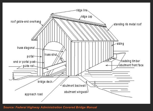
A Typical Covered Bridge
The illustration below shows a typical covered bridge. One distinction that is important when discussing covered bridges is whether it is an authentic covered bridge or a replica.
A bridge is not considered an authentic covered bridge just because it has a roof over it. An authentic covered bridge is built primarily of wood, but the structure that supports the load crossing the bridge is comprised of one of several different kinds of trusses. This differs from modern bridges (and replica covered bridges) where the load is supported by multiple beams running the length of the bridge with a deck (typically made of concrete) on top of that. This is typically called a "stringer" bridge. With authentic covered bridges, the deck is supported by the two trusses on each side of the bridge.
Note that as covered bridges age, and the loads they need to support becoming increasingly heavier, some authentic covered bridges have been modified, by necessity, with modern materials. In some cases, steel stringers have been added to help the trusses support the load. Some bridges have had the floor systems completely separated from the trusses on top of having steel beams installed. Other bridges have had major supporting members replaced with glu-lam beams rather than solid wood members. While this changes the "authenticity" of the bridge somewhat, supplementing the original trusses of a bridge has been recognized as a valid trade-off to destroying a historic structure simply because times have changed. On these pages, it will be noted if a bridge has undergone these types of modifications.
One example of a "covered bridge" in Vermont that is famous, but NOT authentic, is the covered bridge in Quechee Village. It gained national exposure as a victim of the Tropical Storm Irene flooding and touted as an example of how Vermont lost iconic covered bridges to the storm. The fact is, the Quechee bridge was constructed in 1970 and is a typical concrete deck on top of steel stringers like so many other "normal" highway bridges. A covering was constructed over it to make it look like a real covered bridge. Vermont lost only one authentically constructed covered bridge in the Irene flooding: the Bartonsville Bridge.
It should also be noted that a covered bridge does not have to be old to be authentic. The reconstructed Bartonsville Bridge was built in 2012-2013, and despite being brand new, it was constructed using wooden trusses to support the load and is thus authentic.
Truss Types
While there are many components that go into the construction of a covered bridge, the most important components, and the ones that make a covered bridge authentic, are the trusses. The following truss types can be found in Vermont.
Kingpost
The kingpost truss is the most simple truss design. But because of its simplicity, the length that the truss can be built to, and still be effective, is only about 30 feet. This photo of the Pine Brook Bridge in Waitsfield shows some of the main components of a kingpost truss: the kingpost, and kingpost braces (2 of them).
Not visible in this photo is the bottom chord. In a kingpost truss, a long piece of wood runs the length of the truss and the ends of the kingpost braces are tied to it, forming the bottom of a triangle. The reason you can't see the bottom chord in this photo is that the bridge deck (or floor) is built upon it. (See the section on floor construction later on).
The addition of subdiagonal braces and tie (or hanger) rods made of steel strengthens the truss and allows for longer spans... up to 40 or 50 feet. Because of the limitation in span length with a kingpost truss, not many of these bridges survive.

While being able to identify trusses is useful, there are other elements you will see in these photos that are not part of the truss, but bear some amount of explanation. I want to take a minute now to point these out.
Tie beams: Common to all truss designs are tie beams. These beams tie the tops of the trusses together to keep them upright. On kingpost and queenpost truss types, they also tie the tops of supplemental posts together to help support the roof system.
Supplemental posts: These lengths of timber typically extend up from kingpost and queenpost trusses and help support the roof. Other truss types (due to their design) do not have these.
Knee braces: These are short pieces of wood that connect the tie beam to a truss post or other vertical beams. In conjunction with the posts, they help keep the trusses upright and the bridge "true" (not leaning to one side or the other). A problem with knee braces is that they intrude on the clearance of the bridge and are easily damaged by oversize vehicles. Some bridges do away with them but compensate for the lack of knee braces by adding other bracing techniques. Note that they are absent in the Pine Brook Bridge above, but present in the Jaynes Bridge below.
Furring strips: These are simply small strips of wood that are attached to the outside of the truss. The siding is then nailed to these strips. This is so that the siding is not attached directly to the truss, which promotes rot from water being trapped between the two.
Splash boards: These are typically vertical planks of wood that cover the truss on the inside of the bridge similar to how the siding covers the outside. In the pictures illustrating the Multiple kingpost and Town lattice truss examples (below) you can see them extend into the bridge for a couple feet. These are used to help keep the truss dry from blown-in rain and water splashing up from the road.
Guard (or guide) rails: A feature not needed when these bridges were first built, the increasing use of automobiles popularized this addition. All but one of the bridges on this page have them. They are installed either directly onto the inside of the truss, or on the floor, or both. Obviously, these help protect the trusses from errant vehicle operation.
Running planks (or boards): Lastly, although only one bridge on this page has this feature, running boards on the floor are common to many covered bridges. Running boards are laid on the floor where the tires of vehicles travel and the purpose is to save the floor from wear. It is much easier and cheaper to replace running boards when they get worn than to replace the entire floor. They also make the floor a little bit stronger as well.
And now on to more truss types...
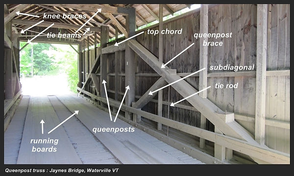
Queenpost
The queenpost truss is essentially a stretched-out kingpost truss. Notice that they have similar components except that instead of one kingpost, there are two queenposts with a top chord strung between them. Both designs have the same sub-diagonals and tie rods for additional strength.
As with all covered bridges, there are tie beams to keep the trusses upright. However, in the past a heavy snow load induced a lean to this particular bridge, despite the tie beams and knee braces. To further brace the bridge, L-shaped steel plates were added tying the queenposts to the tie beams.
The queenpost truss was used often in Vermont, and as you peruse these pages you'll see many examples.
Multiple kingpost (MKP)
This truss is the result of adding more posts to the single kingpost truss design. This affords the ability to create much longer spans than either the single kingpost or the queenpost, but at the cost of more complexity.
The center post of the truss is called the kingpost while all the other verticals are simply called posts. Bracing diagonals run between each consecutive post and all the posts are tied together at the top and bottom by chords. In this photo, the bottom chord is not visible as it is below the floor level.


Burr Arch
The first timber truss system to actually be patented was this truss, by Theodore Burr in 1806. The Burr Arch is essentially a multiple kingpost truss with timber components superimposed on each side in an arch configuration. Depending on the design, the arch continues all the way down to the bridge abutment itself, or ends at and ties into the bottom chord (hidden in this photo by the floor).
The arches can be made of normal timber planks and are tied to each post, providing more load carrying capacity, and thus longer bridge length. There is also a variant that uses lapped timbers, although that is not as prevalent.
The Burr Arch truss was a hit with bridge builders and the majority of the surviving covered bridges in the US are of this design. You wouldn't know it if you visited Vermont's bridges though. The most prevalent truss in use in Vermont's covered bridges is the Town lattice (see below).
I also wanted to use this photo to illustrate a different type of knee brace called a "ship's knee". These braces are made from the stump of a tree. The natural curvature is where a large root is growing outwards from the trunk. It is not the result of assembling different pieces of wood, or carving it from a block. This naturally strong area of the tree is used to provide more clearance inside the bridge, and was originally used within the tight confines of the holds in wooden sailing vessels -- hence the name.
Town lattice
In 1820, Ithiel Town received a patent for this truss design. All truss designs before this one required the use of heavy timbers and skilled carpenters to assemble. The wood planking used to create a Town lattice is relatively light and easy to work with, and didn't require an extremely skilled carpenter to assemble, thus it became a popular truss. Despite the light planking needed, the truss proved to be very strong and some of the longest covered bridges are constructed in this manner.
As shown in this example, the lattice is tied together at each intersection with the use of wooden pegs, or treenails. The term "treenail" (literally a nail made from a tree) is colloquially pronounced "trunnel" and thus the alternate spelling. The lattice also requires two chords at top and two on the bottom (the lower bottom chord is hidden by the floor) in order to keep the lattice from moving.

Other trusses
There are a few more trusses that have been used in covered bridge construction, but not very extensively (at least, not in Vermont). We'll talk about those as we discover them!
Floor Systems
There are a wide variety of floor systems in use in covered bridges. Their design is based mostly on the type of truss in use. Below is just one typical example.
Burr Arch / Multiple kingpost Example
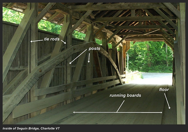
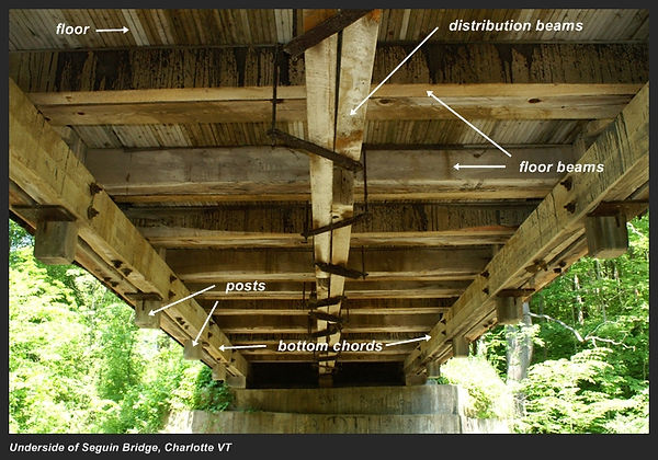
Presented here are photos of the inside and the underside of a covered bridge employing a Burr Arch truss. But unless you look real close, you can't see the arch from the underside, so this example is also very typical of what you would find with a Multiple kingpost truss (without an arch) bridge. The photo illustrates quite clearly why you usually do not see the bottom chord of a truss unless you get down underneath the bridge... because the floor is built off of the bottom chords.
The pieces of wood labeled "posts" in the lower photo are the bottom of the same posts you see in the upper photo. They are notched and connected to the bottom chord similar to how the Lincoln Logs you played with as a kid are locked together. Of course, to make sure they don't come apart they are usually secured together (in this case with large bolts). The rusted metal plates seen adjacent to some of the posts are where tie rods are connected to both the top and bottom chords and tightened for more strength... pulling the two chords towards each other.
Spanning from one chord to the other are floor beams. They are laid on top of the bottom chords and are similar to how floor joists in your house go across your basement to support the floor above. They are typically positioned across the strongest points of the truss -- where the posts and chords are connected. What appears to be water running down the sides of the floor beams I think might be some kind of water repellent or fire proofing treatment that was applied to the floor and dripped through. It also appears with this bridge that the original floor beams were supplemented with 2-by lumber for added strength (most likely sometime after the bridge was built).